Description
1. APPLICATION SCENARIO
◎ Home storage
◎ Island off-grid energy storage
◎ Micro-grid applications
◎ UPS power supply
◎ Power System 220V DC power supply
2. OVERVIEW
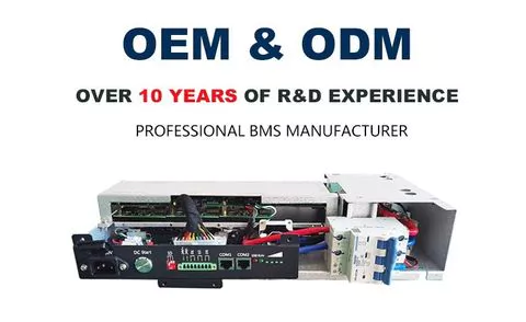
● BMS integrated machine components are composed of BMS main control board, BMU sampling board, high voltage board, switching power supply, Hall sensor, DC contactor, micro switch, power terminal, structural box and wiring harness, etc.; the characteristic is that the main control board Integrate with sampling board and other power devices to keep the system as a secondary architecture. It has the characteristics of compact structure, flexible installation and low cost, and is suitable for integrated installation with small capacity batteries. The BMS integrated machine component is mainly suitable for the charge and discharge management of lithium iron phosphate batteries (LFP). If you need to modify the parameters with other batteries, please contact our company for confirmation.
● Each 15 strings is a battery collection unit, and 75 series batteries have 5 acquisition units.
● 15 probes for every 15 strings, for a total of 15
● current collection uses Hall sensor, safe and reliable, no heat;
● SOC estimation error ≤ 5%;
● 3-digit address dialing to set the BMS address;
● 3-channel relay dry contact output;
● 4-channel contactor expansion and auxiliary contact detection;
● Provide PC software to facilitate the customer to debug the battery system, or modify the system parameters through the host computer;
● Support for parallel use (maximum 7 units);
3.Specification
Product Name: Integrated BMS
Model no.: RBMS07S60S100A
System voltage range: 120 - 228 V DC
Startup mode: DC start (optional AC and DC starter)
Number of battery strings: 60 S(4 x 15 S)
Balance: Equilibrium type, Passive resistance equalization
Balanced current, 100mA ± 10mA(Single cell 3.4V )
Temperature Sampling: Numbers, 12 Battery temperature(4*3)
Sampling accuracy: ± 2℃
Voltage Sampling: Sampling accuracy, Single cell ±20mV
SOC: ≤5%
Communication mode: CAN: 1 channel (communication with PCs / UPS), RS485: 1 channel (communication with upper computer / PCS / UPS)
Bluetooth: optional (android app available)
GPRS: optional,
Display mode: 6-digit LED indicator, including 1-bit fault indication, 1-bit operation indication, 4-bit SOC power indication
HMI display: optional
Hall sensor specifications: 50A/100A
Maximum load of power components
Steady-state:100A
transient state:150A/10S( Adjustable)
Alarm level: 1 Level
Protection level: 2 two levels, Level 1 cut off charge / discharge, Level 2 micro cut-off switch, system power down
Operating Temperature: Charging : -10~75℃, Discharging : -20 to 75℃, Storage : -40 to +75℃
4.Product Feature
1.It is high integrated with less installation space.
2.Long life cycle, >3000 times at 80% DOD.
3.It without heavy metals and environment friendly.
4.Maintenance free,there is no memory effect.
5.Internal BMS with full protection,battery has high voltage protection with higher reliability.
6. Master and Slave all in one.
5.BMS working status description
Start-up process
Make the BMS in the shutdown state and complete the connection with the BMS. After the BMS is assembled, turn the micro disconnect switch on the chassis to "on", then press the start button (DC start), and the BMS will enter the self-test. If the self-test is normal, you can hear the sound of the contactor closing, the green light on the chassis is on for a long time (it will flash if there is external communication), and the start is completed.
Shutdown/transport status
After the system starts and starts normally, turn the micro disconnect switch to "off" to turn the BMS into shutdown / transport status. If the BMS is not used for a long time, the BMS must be in this state.
Working State
After the BMS is started, the power supply of the BMS is detected to work normally. Those who do not enter sleep automatically
Dormancy state
The system does not sleep by default.
Fault condition
If the following three conditions are detected during BMS self-test, it will enter into the failure mode, and manual intervention is required to eliminate the failure.
1.Internal power failure: Long red light
2.Internal communication failure (communication error between MCU and AFE), Long red light
3.Single section voltage is higher than 4.1V or lower than 0.5V, or the differential pressure is greater than 2.5V, Long red light
4.The temperature is lower than - 30 ℃ or higher than 100 ℃, or the temperature difference is greater than 30 ℃. Long red light
5.Others: Long red light
Equalization function
BMS uses the resistor circuit to balance the cell. The cell voltage of the battery pack reaches 3.5V and the voltage of the cell is higher than the lowest single-segment voltage of 50mV, or the cell voltage exceeds 3.65V to turn on the equalization function. Time (except for overcharge and full charge) equalization stops.
Note: The equalization voltage can be set.
- High voltage BMS
- lifepo4 bms
- samrt bms
- power solution
- 15s 16s battery management system
Production Capacity:
2000
Delivery Timeframe:
Within 30 Days
Incoterms:
CIF - Cost, Insurance and Freight
DDP - Delivered Duty Paid
DDU - Delivered Duty Unpaid
EXW - Ex Works
FOB - Free on Board
Packaging Details:
一套入一箱
More about
High voltage BMS wholesale/FOB
100-200
Employees
500K - 1M
Sales volume (USD)
90%
% Export sales
Year
Established
Business type
- Industry / Manufacturer
- Distributor / Wholesaler
Keywords
- High voltage lithium battery management system
Contact and location
-
Connie Kang
-
+86 xxxxxxxx
-
长沙 / 湖南 | China


